

Guide · Drawings
What Belongs on a Reflected Ceiling Plan
On a commercial fit-out, the reflected ceiling plan is where the project actually gets coordinated. Lighting, air, sprinklers, structure and the grid all compete for the same few hundred millimetres above your head, and the RCP is the only drawing where they are all shown together. It is also the drawing most often missing from an existing-conditions set, and the one most often assumed rather than measured. This guide covers what an RCP is, why it is drawn upside down on purpose, what conventionally goes on one, and what it takes to produce a reliable one for a building that already exists.
The short answer
A reflected ceiling plan is the ceiling drawn as though a mirror were lying on the floor reflecting it back down. You are looking at the ceiling, but in the same orientation as the floor plan beneath it — north stays north, left stays left, and a fixture at the top-right of the RCP is directly above the top-right of the floor plan. That single convention is what lets a designer lay the two drawings over one another and see what is above what.
The drawing that looks up by looking down
A plan drawing is a horizontal cut through a building, viewed from above. That works for walls, doors and furniture, which all sit below the cutting plane. The ceiling does not. If you drew it the obvious way — by turning around and looking up — everything would be mirrored relative to the floor plan, and the two drawings could never be read together. A light fixture on the left of one would be on the right of the other.
The reflected convention solves this. Instead of looking up at the ceiling, you imagine a mirror on the floor and draw its reflection, which puts the ceiling into exactly the same orientation as the plan below it. The drawing is still labelled and read as a plan. It simply shows what is overhead rather than underfoot, and it does so in a coordinate system that agrees with every other plan in the set.
This matters more than it sounds. A fit-out is a stack of decisions made by people who are not in the same room: an interior designer placing partitions, an electrical consultant placing luminaires and switching, a mechanical consultant placing supply and return, a sprinkler contractor placing heads. Each of them works on their own drawing, and the only thing making those drawings commensurable is that all of them share the floor plan's orientation. Break that and the coordination breaks silently — nobody sees the clash until something is already installed.
The other thing the RCP does is make the void legible. Between the underside of the grid and the underside of the structure sits a zone that carries ducts, sprinkler main, conduit, cable tray, structure and whatever else was put there over thirty years of tenancies. The RCP is the drawing that records where the accessible surface of that zone is, what is hung from it, and how much room there is above it.
- Structure above
- Clear void between them
- Services competing for the depth
- Finished ceiling
- Slab and floor drainage
What conventionally belongs on a reflected ceiling plan
Contents vary by project and by who is drawing. This is the set that turns up on most commercial fit-out RCPs, and what each item is actually there to answer.
| On the drawing | What gets recorded | What it settles |
|---|---|---|
| The ceiling grid | What gets recordedTile module, the direction the grid runs, and where its layout originates in the space | What it settlesWhether a new partition lands on a grid line or cuts a tile in half, and how much of the ceiling has to be rebuilt |
| Ceiling types and materials | What gets recordedSuspended acoustic tile, gypsum board, exposed structure or open plenum, area by area | What it settlesWhat can be cut into, what has to be patched and painted, and what cannot be touched without a trade on site |
| Ceiling heights | What gets recordedHeight above finished floor for each ceiling zone, usually noted as AFF | What it settlesWhether a tall element, a piece of equipment or a millwork run actually fits under the ceiling it is drawn against |
| Bulkheads and soffits | What gets recordedThe dropped areas, their extents and their own separate heights | What it settlesThe single most common reason something that fits the nominal ceiling height still does not fit where it is going |
| Light fixtures | What gets recordedType, size and position of each luminaire, and how the fixture sits in or on the ceiling | What it settlesThe lighting layout, the circuiting behind it, and what has to move when a partition moves |
| Air devices | What gets recordedSupply diffusers, return grilles and registers, with their positions in the grid | What it settlesWhether each new room has supply and return, or is a sealed box with neither |
| Sprinkler heads | What gets recordedHead positions relative to the grid, and head type where it is visible | What it settlesWhether a new wall leaves a room unprotected or a head stranded in the wrong place |
| Life-safety and low-voltage devices | What gets recordedDetectors, exit and emergency lighting, speakers, sensors and ceiling-mounted devices | What it settlesCoverage that has to be maintained when the layout changes, and devices that have to be relocated rather than removed |
| Access panels and hatches | What gets recordedWhere the void is reachable without dismantling the ceiling | What it settlesHow anything above the ceiling gets serviced once the fit-out is finished |
| Ceiling-mounted equipment | What gets recordedProjectors, fans, cassette units, mounts and anything else hanging from the ceiling plane | What it settlesLoads, clearances and the things that are easy to forget until demolition uncovers them |
What a particular drawing set has to show is a decision for the design team running the project, and where a permit is involved, for the authority having jurisdiction. This is a description of common practice, not a checklist for a submission.
What an RCP deliberately leaves out
Half of reading a drawing type is knowing what it is not telling you. An RCP is a narrow drawing on purpose.
Furniture and floor finishes
Anything sitting on the floor belongs on the plan, not here. The RCP stays quiet about the floor so that the ceiling is readable, which is why the two drawings are used together rather than merged.
Door swings
Walls appear, because the ceiling stops at them and you need to see the rooms. Doors are usually shown as openings without their swing arcs — the swing is a floor-level fact and would clutter a drawing that is already dense.
What is inside the void
An RCP records the ceiling plane and what is visible in it. Ducts, conduit and pipework above the tile are the mechanical and electrical drawings' job, and on an existing building they are only ever documented as far as they can actually be seen.
Anything it could not see
This is the honest limit on every existing-conditions RCP. A ceiling void that is sealed, inaccessible or behind a tenant's locked area is recorded as unverified rather than guessed at. A drawing that quietly fills gaps is worse than one that marks them.
Where the ceiling gets recorded
The ceiling is captured in the same site visit as the floor, from the same scan positions. It is not a second trip.
Why the ceiling is the part most often guessed at
Measuring a floor plan by hand is tedious but straightforward. Measuring a ceiling by hand is neither. Every height has to be taken overhead, often from a ladder, often in a space with people working in it. Every fixture position has to be located in two dimensions relative to something that is itself being measured. Every bulkhead has its own extents and its own height. It is slow, awkward work, and it is exactly the kind of work that gets sampled rather than surveyed — three heights taken, one number written down, and the whole floor drawn as though the ceiling were flat.
It usually is not flat. Older commercial buildings accumulate dropped areas around structure, around later mechanical runs, and around whatever the last three tenants built. A floor with one nominal ceiling height can have four real ones, and the difference only surfaces when something is being installed.
A scan changes the economics of this. The same setup that records the walls records the ceiling plane, the fixtures in it and the heights across the whole floor, because the instrument does not care which direction it is pointing. Nothing is sampled. The heights in the finished drawing are read out of the measured data afterwards, in a chair, rather than taken overhead on site.
How an existing-conditions RCP gets produced
The same four stages as any measured set, with the ceiling handled as part of the capture rather than as an add-on.
Agree what the ceiling scope covers
Which areas, and how far into the services the drawing goes. This is settled before the visit, because it is a drafting decision as much as a capture one — the capture records what is there either way, but the drawing has a defined scope.
Capture floor and ceiling in one pass
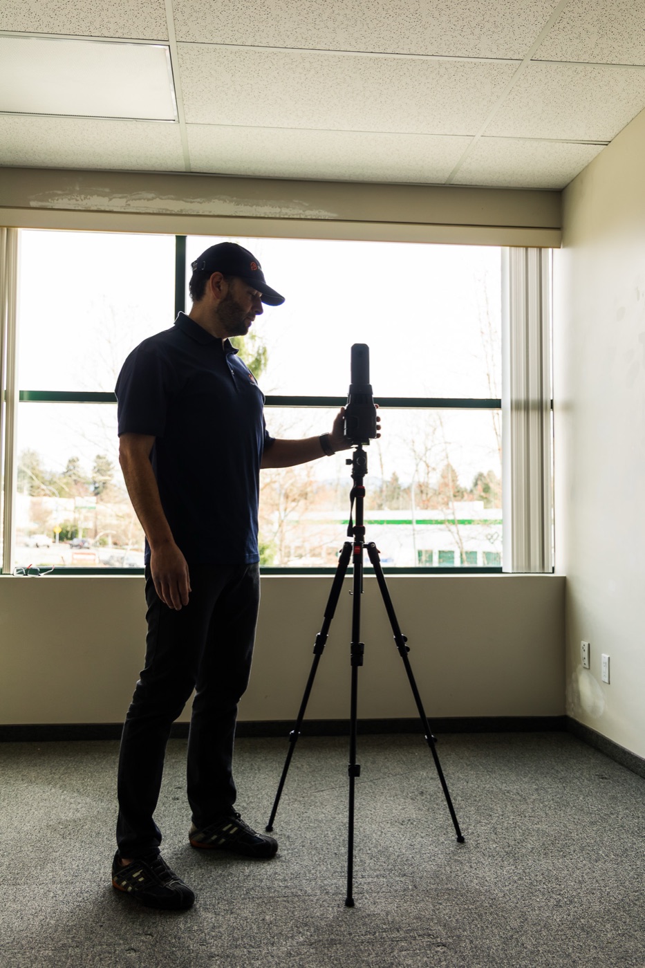
The iGUIDE PLANIX moves through the space one position at a time, recording LiDAR geometry and 360° imagery together. Grid, fixtures, diffusers, sprinklers and heights come out of the same dataset as the walls, which is what makes an RCP possible without a second visit.
Draw the ceiling against the measured data
Fixture positions and grid layout are drafted from the point cloud and the imagery, not traced from an older set. Where a previous drawing disagrees with what was measured, the measurement wins and the discrepancy is flagged rather than smoothed over.
Mark what could not be verified
Inaccessible areas, sealed ceilings and anything obscured are noted on the drawing as unverified. A design team can work around a marked gap. It cannot work around a gap it does not know is there.
Where the ceiling sits in a layered CAD set
In a delivered CAD file, ceiling information belongs on its own layers rather than mixed into the floor-plan geometry. That separation is what lets a consultant turn the ceiling on over the plan, or turn the plan off and work on the ceiling alone, without editing anyone else's linework.
The published convention most North American offices reference is the AIA CAD Layer Guidelines, which the AIA agreed in July 1997 to fold into the United States National CAD Standard. Layer names are built from a discipline designator, a major group, an optional minor group and a status field — the guidelines' own worked example is A-WALL-FULL, meaning architectural, wall, full height. Ceiling content sits under the architectural discipline with CLNG as its major group, and minor groups subdivide it by element. The published standard carries the full list; it is worth reading from the source rather than from anyone's summary, including this one.
In practice most firms of any size already have their own layer convention, whether that is an in-house standard or something close to the AIA guidelines, and a delivered file should arrive in it. Send the standard, a template or a sample drawing when the job is booked and the ceiling layers come back in that structure. Where there is no documented standard, which is common and not a problem, the set is delivered in a clean conventional layer structure a drafter can pick up without a legend.
Who reads the RCP, and what each one wants from it
The same drawing answers a different question for each party on the project, which is why it is worth getting right once rather than four times.
The interior designer
Where the grid runs and where it originates, so partitions can be set against it and the ceiling does not have to be rebuilt around a wall that lands mid-tile.
The electrical consultant
Existing luminaire types and positions, and what is already circuited, so a new lighting layout is a modification of something real rather than a design over a blank ceiling.
The mechanical consultant
Where supply and return currently land, and how much depth exists above the grid. A new room with no air device in it is one of the cheapest problems to catch on a drawing and one of the most expensive to catch on site.
The general contractor
What comes down, what stays, and what the ceiling is actually made of area by area. Demolition scope on a fit-out is largely a ceiling question.
The landlord or property manager
A current record of the base building condition at the ceiling, which is the layer least likely to be documented anywhere and most likely to be argued about at the end of a tenancy.
The next project
A measured RCP outlives the fit-out it was drawn for. The next tenant's design team starts from a real ceiling instead of commissioning the same survey again.
What the ceiling capture delivers
The same specification as the floor plan, because it comes out of the same scan.
- Measurement accuracy
- ±10mm
- Camera
- 60MP 360°
- Ceiling visit
- Same pass
- Floor plans delivered
- 1–2 days
- CAD & BIM delivered
- ~1 week
- Scope tier
- Shell 360
Where an RCP sits in our scope
Reflected ceiling plans are part of Shell 360, the middle of the three detail levels in our estimator. Base 360 is the measured floor plan and CAD — walls, columns, doors, windows and stairs — and suits early planning, feasibility and test fits. Shell 360 adds reflected ceiling plans, ceiling and sill heights, visible MEP, millwork elevations and material finishes, which the estimator describes as the level for standard interiors, renovations and permit sets. Full 360 adds a Revit model and freestanding furniture and fixtures on top of that.
Ceilings are the most common difference between two quotes that otherwise look identical, and the most common reason a set arrives without the drawing the mechanical consultant was waiting for. It is worth deciding on ceilings at booking rather than after delivery — everything captured in one pass is drafted in one pass, and adding ceilings afterwards starts a new round of drafting on data that may already need a second visit to extend.
What level of detail a particular project needs is not our call. That is a decision for the architect or designer running it, and where a permit is involved, for the authority having jurisdiction. What we can do is capture the ceiling accurately enough that the decision is made against a real building rather than against an assumption.
See a measured set before you commit
The clearest way to judge an existing-conditions RCP is to look at one, alongside the floor plan it was drawn to sit under.
Opens the sample set on our home page — floor plans, CAD and a 3D tour of real commercial space.
Common questions
Because it is drawn as the reflection of the ceiling in an imaginary mirror lying on the floor, rather than as a view looking up. That keeps the ceiling in the same orientation as the floor plan, so the two drawings can be read together and overlaid.
In commercial practice the terms are used interchangeably, and almost every ceiling plan you will see is a reflected one. The distinction only matters if someone has genuinely drawn the ceiling as a view from above, which would put everything mirrored relative to the floor plan.
That is a question for the architect or designer running the project, and where a permit is involved, for the authority having jurisdiction. As a general pattern, projects that touch lighting, air distribution, sprinklers or partitions that meet the ceiling tend to need one, and projects that do not usually do not.
Yes — that is the normal case. The ceiling is measured directly from the scan, so the drawing does not depend on an older set existing or being accurate. Where an old drawing does exist, it gets checked against the measurement rather than trusted.
No. Grid, fixtures, diffusers, sprinklers and heights are captured in the same pass as the floor, from the same scan positions. It is the drafting scope that changes, not the site work.
They come out of the same registered scan data as the rest of the drawing, captured at ±10mm, and are read off in the office rather than taken overhead on site. Each ceiling zone gets its own height rather than the floor being drawn to one nominal figure.
Yes. Send the standard, a template file or an example drawing when you book and the set comes back in that structure. Without one, we deliver a clean conventional layer structure that separates ceiling content from the floor-plan geometry.
We record what is visible. Ducts, conduit and pipework that can be seen — through open plenum, lifted tile or accessible areas — are captured as visible MEP. A sealed void is marked as unverified rather than drawn from assumption.
Keep reading
Get the ceiling measured, not estimated
Put your approximate area and detail level into the estimator to price a Shell 360 scope for your building, then book the visit in the same flow.