

Guide · Measurement Methods
LiDAR vs Matterport vs Tape: What Each One Measures
People comparing ways to document an existing building usually arrive at the same three options: a tape measure, a Matterport scan, or LiDAR. It looks like a choice between three methods. It is actually three different kinds of name — a technique, a brand and a sensor — and the brand's current camera uses the sensor. The comparison that decides whether a drawing can be built from is narrower and more useful: what tolerance an instrument measures to, how that figure is stated, and what is left behind once the surveyor has gone. This guide sets out each one using the manufacturers' own published figures, so you can match the instrument to the work rather than to the marketing.
The short answer
LiDAR is a way of measuring distance with a laser. Matterport is a company that makes capture cameras, and its current professional camera, the Pro3, measures with LiDAR. A tape measure is a technique whose accuracy depends mostly on the person holding it. So the real question is not which of the three to use but which tolerance your drawing needs. Matterport publishes ±20mm at 10 metres for the Pro3. iGUIDE publishes ±10mm camera-to-wall for the PLANIX we use. Survey-grade terrestrial scanners work to ±1–3mm. A phone's LiDAR is far looser than any of them. For most commercial and industrial as-builts, a tripod-mounted LiDAR scanner like the PLANIX is the right balance of accuracy, speed and cost, and it is what we use.
Three names that are not three methods
The comparison gets muddled because the names sit at different levels. "Tape" describes how a measurement is taken: one distance at a time, between two points a person chose. "LiDAR" describes a sensor: a laser that times its own reflection to measure distance, fired many thousands of times a second across a whole room. "Matterport" is neither. It is a company, and over the years it has sold cameras built around different depth sensors, alongside an app that captures with a phone.
Its current professional camera, the Pro3, is a LiDAR instrument. So is the iGUIDE PLANIX we scan with. A search for "LiDAR vs Matterport" is therefore often a search for something slightly different: whether a 360° tour camera measures well enough to draw from, or whether a job needs a dedicated survey scanner. That is a real question, and it has a real answer. It just is not a question about brands.
The useful way to line the options up is by instrument class, from loosest to tightest, with the tolerance each manufacturer publishes for its own equipment. That is what the table below does. It is worth reading the tolerance column and the right-hand column together, because each of these instruments is the correct choice for some job, and each is the wrong one for others.
The ways to measure an existing building, loosest to tightest
Tolerances are the ones each manufacturer publishes for its own equipment. They are not independent tests. They are stated under different conditions, which the next section explains.
| Instrument | How it measures | Published tolerance | What it is the right tool for |
|---|---|---|---|
| InstrumentPhone or tablet LiDAR | How it measuresA small LiDAR sensor built into a consumer device, usually driven by a capture app. | Published tolerance±100–200mm — Matterport's published figure for smartphone LiDAR | What it is the right tool forA quick visual record, a rough layout, or a marketing tour of a small space. Not a base for design or fabrication. |
| InstrumentTape and hand sketch, or a handheld laser distance meter | How it measuresOne distance at a time between points the surveyor chooses, written onto a sketch and drawn up later. | Published toleranceNo single figure. Each shot can be very precise; the drawing's accuracy depends on how the shots were chained together and what was never measured. | What it is the right tool forA small, simple, rectangular space measured by an experienced person, where only a handful of dimensions matter. |
| InstrumentMatterport Pro3 | How it measuresA tripod-mounted camera pairing LiDAR with 360° imagery, captured one setup at a time. | Published tolerance±20mm at 10m — Matterport's published figure | What it is the right tool forIn Matterport's own words: documentation, planning, coordination and marketing, including as-builts, lease audits and virtual tours. |
| InstrumentiGUIDE PLANIX R1 | How it measuresA tripod-mounted camera pairing LiDAR with a 60MP 360° camera, captured one setup at a time. This is the instrument we use. | Published toleranceTypically ±10mm camera-to-wall on walls 60cm or longer; ±25mm across the raw point cloud out to its 40m range — iGUIDE's published figures | What it is the right tool forMeasured floor plans, reflected ceiling plans, CAD and Revit existing-conditions models, area calculations and fit-out design. |
| InstrumentSurvey-grade terrestrial laser scanner | How it measuresA dedicated tripod scanner capturing a dense point cloud, usually registered to survey control. | Published tolerance±1–3mm — the range Matterport cites for survey-grade tripod scanners | What it is the right tool forStructural and fabrication-level work: steel, prefabrication layout, clash detection in dense plant, forensic measurement. |
Figures read from Matterport's "How accurate is LiDAR?" article (July 2026) and iGUIDE's PLANIX R1 technical specifications, September 2026. Manufacturers revise specifications; check the current figure before relying on one.
What a tolerance figure does and does not tell you
Two figures in that table look directly comparable and are not. Matterport states the Pro3's accuracy as ±20mm at a range of 10 metres. iGUIDE states the PLANIX as ±10mm from camera to wall on a wall at least 60cm long, and separately as ±25mm across the raw point cloud out to its full range. One describes raw depth at a stated distance; the other describes a measured wall and then gives a looser figure for the raw data. Neither is misleading. They are answers to slightly different questions, and a buyer who lines them up as though they were the same measurement will draw the wrong conclusion in one direction or the other.
Range matters for every instrument on the list. A reading taken from a metre away is almost always tighter than one taken from twenty metres, which is why a scan of a large floor is captured from many positions rather than one, and why a small room scans more consistently than a deep warehouse bay. A stated tolerance is a statement about good conditions. Glass, mirrors, polished floors, black surfaces and bright sunlight all affect laser measurement, and a competent surveyor plans setups around them.
Finally, a tolerance describes a measurement, not a drawing. Somebody still drafts the drawing from the captured data, and they make decisions as they go: whether a wall that is 6mm out of plumb is drawn as it is or as a straight line, whether a column that is not quite square is drawn square, where exactly a finished face is on a textured surface. Two firms using the same instrument can hand over drawings of different quality. So the question worth asking a provider is not only "what is your tolerance?" but "how is that figure stated, and how do you draft from it?"
How a tape survey actually goes wrong
Tape measurement has a reputation it does not entirely deserve. An individual reading from a good handheld laser distance meter is very precise, and an experienced surveyor measuring a simple room will produce a drawing that is perfectly adequate for plenty of purposes. The weakness is not the instrument. It is what happens between readings.
A hand survey is a chain. Each dimension is taken from something the last dimension located, so a small error early in a run is carried into every measurement that follows. Across one room that is harmless. Across a long corridor of offices, or twenty bays of racking, it accumulates into an end wall that does not close, and nothing on the finished drawing shows where the error went in.
The second weakness is assumption. A tape survey records the dimensions someone decided to take, and the drawing fills the gaps with straight lines and right angles, because that is how drawings are made. Walls that are slightly out of square, a floor that falls towards a drain, a soffit that steps partway along a room — these are exactly the conditions that surprise a fit-out, and they are exactly the ones a chain of point measurements tends to miss.
The third is what survives the visit. When the ceiling height over the loading dock turns out to matter three weeks into design, a tape survey has nothing to say about it, because nobody measured it. Somebody drives back. That return trip is the real cost of a tape survey on a commercial job, more often than its tolerance.
Matching the tolerance to what will be built from the drawing
The tolerance a drawing needs is set by what is going to be made from it. Your design team sets that figure. These are the broad bands, not a specification for any particular project.
A marketing tour or listing plan
The job is to show a space to someone deciding whether to visit it. Proportions and layout matter; millimetres do not. A tour camera, or for a small space a phone, is often enough.
Space planning and test fits
Will the layout fit, roughly how many workstations, does the meeting room go here or there. Tens of millimetres rarely change the answer. A tour camera or a careful hand survey usually suits.
Existing-conditions base for design
The drawing an architect or designer draws a proposal over, and often shows to a reviewer as the existing condition. Errors here are carried into every sheet drawn on top, so a measured base at around ±10mm is where most commercial design work sits.
Area calculations
An area figure multiplies a small dimensional error across a whole floor, and rent is charged on that figure. Measured wall positions matter more than they appear to. The measurement standard itself is set by the lease, not by the instrument.
Millwork and casework
Joinery made off site to fit a room that already exists. The drawing is acting as a specification, so its errors turn up as gaps or as pieces that do not go in. Tighter is better, and the fabricator will usually verify critical dimensions on site as well.
Steel, prefabrication and clash detection
Work where a few millimetres decides whether something fits or clashes. Matterport's own guidance is that sub-5mm work needs a survey-grade scanner, and that is the right tool for it.
Tolerance is half the comparison. Coverage is the other half.
It is easy to read a comparison like this one purely as a race to the smallest number. For most commercial projects that is the less important half. The other half is coverage: how much of the building was recorded at all.
A tape survey records the dimensions someone decided to take. Every LiDAR instrument on the list, from a phone to a survey scanner, records everything in its line of sight from every position it was set up in, whether or not anyone thought it would matter. That is why a scanned building can answer a question weeks later that nobody asked on the day, and a hand-measured one cannot.
Tour cameras add a second kind of coverage: the imagery is captured together with the measurements and registered to it. A design team can open the tour, look at the condition in question, and see it in context — the pipe run, the bulkhead, the unexpected door — without anyone going back to site. For a fit-out in an occupied building, where every visit has to be arranged around a tenant, that is frequently worth more than the difference between one tolerance band and the next.
Choosing a method for a particular project
Four questions settle almost every case. The first two are for your own team; the last two are for whoever you are thinking of hiring.
Ask your design team what tolerance they are working to
The architect, designer or engineer who will draw over the survey knows what their work needs. If nobody has said, ask before booking anything — it decides the instrument.
Ask what will be made from the drawing
A drawing that will be looked at and a drawing that will be fabricated from are different documents. If joinery, steel or prefabricated components will be built to it, say so up front.
Ask a provider how their tolerance is stated
At what range, against what, and whether it describes a measured wall or a raw point. A firm that answers with a specific instrument and a specific figure is telling you something useful. A firm that answers "very accurate" is not.
Ask what you receive besides the drawing
A PDF, a layered DWG, a Revit model, a 3D tour, a point cloud. What arrives decides whether the next question can be answered from a desk or needs another visit.
Why we measure at ±10mm, and the one job that needs more
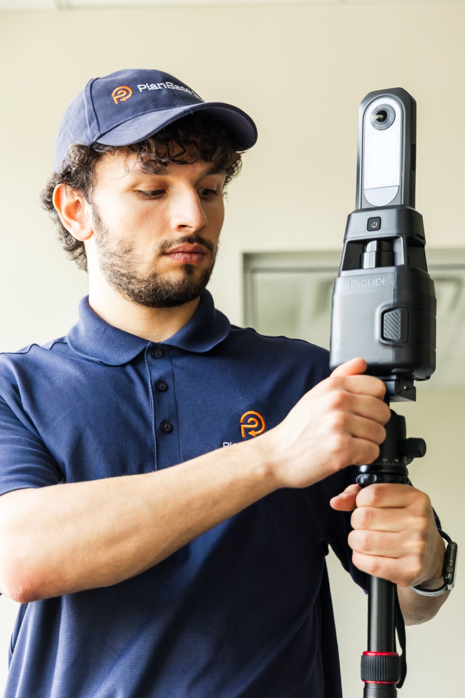
PlanBase 360 captures with an iGUIDE PLANIX R1: LiDAR paired with a 60MP 360° camera, set up position by position through the building. We quote ±10mm, which is iGUIDE's published camera-to-wall figure, and draft the drawings from the captured data rather than from any earlier set. Floor plans and the 3D tour follow the site visit in one to two business days, with CAD and BIM deliverables within about a week, in DWG, RVT and PDF.
That band is the sweet spot for the work most commercial and industrial projects actually commission: existing-conditions bases for tenant improvements, reflected ceiling plans, area calculations, and Revit models of buildings that were never modelled. It is also tight enough for most fit-out joinery to be designed against, with the fabricator verifying the critical dimensions as fabricators always do.
It is tighter than a tour camera's published figure and far tighter than a phone or a tape run across a long floor, and it arrives with a walkable tour and a drafted drawing set rather than a tour alone. It is not survey-grade, and we do not describe it that way. If your project needs millimetre-level verification — structural steel, prefabricated assemblies, clash detection in a crowded plant room, or anything measured for a dispute — that is the one case where a terrestrial laser scanner is the right instrument. For everything else on the list above, ±10mm LiDAR is what we would recommend, and what we deliver.
Judge a measured set for yourself
Tolerances on a spec sheet only go so far. The sample page has floor plans, measured areas and the 3D tour from a delivered project, so you can see what the ±10mm band looks like as a finished drawing.
Opens the sample page — floor plans, an iGUIDE tour and measured output from real work.
Common questions
Matterport's current professional camera, the Pro3, uses LiDAR. Matterport has sold cameras built around other depth sensors in the past, and it also offers capture with a phone, so "a Matterport scan" can mean different instruments with different tolerances. Ask which device captured the space.
Matterport publishes ±20mm at 10 metres for the Pro3 and describes as-builts among the uses it suits, while stating that sub-5mm work needs a survey-grade scanner. Whether ±20mm is enough for your drawing depends on what will be built from it, and your design team is the right judge of that.
For a rough layout or a quick visual record, often yes. For a design base, usually not: Matterport's own published figure for smartphone LiDAR is ±100–200mm, which is several times looser than a tripod tour camera and far looser than a survey scanner.
For a small, simple space measured by an experienced person, it can be perfectly adequate. Its weaknesses are error that accumulates along a chain of measurements, conditions nobody thought to measure, and a return trip when a new question comes up. Those weigh more heavily as a building gets larger and more subdivided.
It usually refers to dedicated terrestrial laser scanners, which Matterport's own article puts at ±1–3mm, often registered to survey control. They are the right tool for fabrication-level and structural work. Tour cameras such as the Pro3 and the PLANIX sit in a looser band and are built for documentation.
An iGUIDE PLANIX R1, which pairs LiDAR with a 60MP 360° camera. iGUIDE publishes a typical camera-to-wall uncertainty of ±10mm on walls 60cm or longer, and ±25mm across the raw point cloud out to 40m. We draft the drawings from that data and deliver PDF, DWG and RVT, plus the 3D tour.
Keep reading
Measure once, to a tolerance you can draw from
Book the scan online with an instant estimate. Measured plans and the 3D tour in one to two business days, CAD and BIM within the week.